Construct a G5RV
Constructing a G5RV Standard G5RV Antenna
Parts:
- 26m of figure 8 cable
- PVC “T” joiner
- 100 pieces of black 12mm poly pipe, each 2cm long
- 13mm heatshrink (not absolutely necessary, but may improve the durability of the antenna - see fedline instructions below)
- PL259 coaxial connector
- 2 egg insulators
- A 10cm long piece of 50mm PVC pipe
- 80cm of RG58 Coaxial Cable
- Silicon and silicon gun
- Glue gun and glue sticks
- Self amalgamating tape
Instructions (1) - The dipole
1. Carefully split apart the figure 8 cable. Take care not to stretch it as this may damage the wires inside.
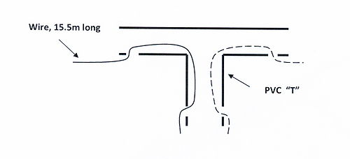
2. On the PVC “T” joiner drill 4 holes as shown in the diagram below.
3. Feed 15.5 m of one of your wires through two holes as shown in the diagram below. Take care when you measure the 15.5m that you have done it accurately.
4. Do the same on the other side of the joiner with the other wire
Notes: 1. The two 15.5m wires are known as the “radiators”. These are where most of the power that comes from your transmitter will be radiated from
2. It is important that the wires are firmly secured into the T joiner. Once we have the feedline constructed, we will fill the T joiner with silicon sealer.
3. The T joiner is the centre of the G5RV. This is usually where the antenna is suspended from.
Instructions (2) – The feedline
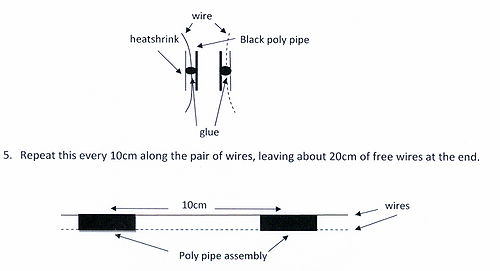
1. Start about 10cm below the “leg” of the T joiner. Carefully apply a drop of glue about half way along one of the 2cm pieces of poly pipe. Press one of the wires into the drop of glue and wait until it has set. CAUTION – THE GLUE IS HOT
2. Do the same with the other wire on the opposite side of the poly pipe.
3. Get a piece of heatshrink and feed both wires through it until you can get it over the poly pipe with the wires attached.
4. Use a heat gun to shrink the tubing over the poly pipe and wires
Instructions (3) – the balun (current transformer)
1. Drill a hole in each end of the 50mm PVC pipe. Feed the coaxial cable through one of the holes, leaving about 15cm hanging out of each end of the pipe.
2. Wind 4 close-together coils onto the pipe and feed the coaxial cable through the other hole. You should have about 15cm of coaxial cable hanging from each end of the pipe.
3. Use some hot glue to keep the coils tightly together.
Instructions (4) – Putting it all together
1. Measure your feedline and cut it off to a length of 9.5m from the T joiner
2. Strip the ends of the feeder wires for about 1cm
3. Put a piece of the small heatshrink over each wire. We will need this later.
4. Strip one end of the coaxial cable on your balun.
5. Twist the braid into a point on one side of the cable
6. Solder one of the feeder lines to the centre wire of the coaxial cable and the other feeder line to the outer braid.
7. Slide the two pieces of heatshrink down the wires to cover your solder joints and shrink the tubing with a hot air gun.
8. Slide the small metal tube from the PL259 connector onto the other end of your balun coaxial cable
9. Strip the other end of the coaxial cable
10. Solder the inner wire of the coaxial cable to the central pin of the connector
11. Fold the braid down, slide the metal sleeve over it and crimp it with the crimping tool
12. Cover the coaxial plug with self amalgamating tape.
13.Tie an egg insulator on the end of each of the radiators.
Done!!


