Log Periodic (LPDA)
Related wiki pages Bands, Propagation, Antennas, Gain, SWR
Log Periodic Dipole Array - (LPDA)
What is it?
The log periodic Dipole Array (LDPA) is a multi-frequency antenna composed of a series of driven elements parallel to each other. One of the advantages of the LDPA is that each on each frequency that it is designed for the following essential characteristics of an effective antenna remain almost constant:-
How does it work?
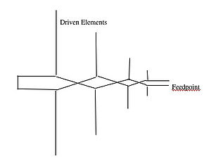
The basic shape of an LPDA is shown in the diagram below. All the elements are driven as all are connected to the feedpoint. The construction is a series of parallel dipoles of different lengths and different spacings. At a particular frequency, one of the elements will be resonant and the others will not.
As can be seen in the diagram, one unusual feature of an LPDA is the "crossing over" of the feed lines for each successive dipole in the array - giving a relative phase shift at each dipole of <math>180^0 </math> compared to those closest to it.
The LPDA is capable of providing maximum:minimum frequency ratio of nearly 2:1 when appropriate design parameters are used.
Typically, Gain is in the region of 7.4dBd
Why is it called Log periodic?
In this antenna the electrical properties vary logarithmically with the frequency.
Two variables (selectable and adjustable by the designer) affect the electrical characteristics of the LPDA:
<math> \tau </math> known as the design parameter and
<math>\rho</math> known as the relative spacing constant.
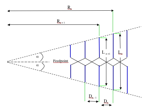
In the diagram below,
<math> \tau = \frac {R_n+1} {R_n}= \frac {D_n+1} {D_n}= \frac {L_n+1} {L_n} </math>
and
<math> \rho = \frac {1-\tau}{4tan\alpha} = \frac {D_n}{2L_n} </math>
Optimum design of an LPDA requires <math> \tau </math> to be set in the range <math> 0.8 \leq \tau \leq 0.95 </math>
maximum gain is achieved by balancing <math> \tau </math> and <math> \sigma </math>, but has been found to occur when: <math> \sigma = 0.243\tau - 0.051 </math>
How do I design an LPDA?
The ARRL Antenna Book lists steps in LPDA design:
External Links
| Antennas | |
| Design | Beam * Dipole * Dish or Parabola * DDRR * Log Periodic (LPDA) * Loop * Mobile and portable * Omnidirectional * Panel * Quad and Quagi * Screwdriver * Small tuned loop * Vertical * Yagi-Uda * Wire and random wire antennas |
| Installation | Antenna Tuners * Capacity hats and loading coils * Cavity filters * Coaxial Cable * Feedlines * Rotators * Towers and Masts * VK2ACY - G5RV coupler |
| Theory | Front-to-back ratio * Impedance matching * SWR * Tower design * Vertical Antenna efficiency * Wire comparison tables |

