SWR: Difference between revisions
(new standing wave diagram) |
m (fixed info) |
||
| Line 41: | Line 41: | ||
<math> P_f = </math> forward power - towards the antenna | <math> P_f = </math> forward power - towards the antenna | ||
== | ==Some myths about SWR== | ||
1) I can calculate SWR to a ratio of 1.000 : 1 | 1) I can calculate SWR to a ratio of 1.000 : 1 | ||
| Line 59: | Line 59: | ||
Your transmissions are most likely to interfere with other services when: | Your transmissions are most likely to interfere with other services when: | ||
* your transmitter puts out a broad band signal rather than a narrow band signal | * your transmitter puts out a broad band signal rather than a narrow band signal | ||
* the TV station that your neighbour is watching is on a frequency that is a harmonic of your TX frequency | * the TV station that your neighbour is watching is on a frequency that is a [[harmonics |harmonic]] of your TX frequency | ||
* you are using high power into a beam that is at the same height | * you are using high power into a beam that is at the same height and directed towards your neighbours TV antenna | ||
==How is SWR calculated?== | ==How is SWR calculated?== | ||
Revision as of 23:45, 25 August 2008
Related wiki pages Antennas, Gain, Propagation, Bands, harmonics, Front-to-back ratio
Standing Wave Ratio - (SWR)
What is SWR?
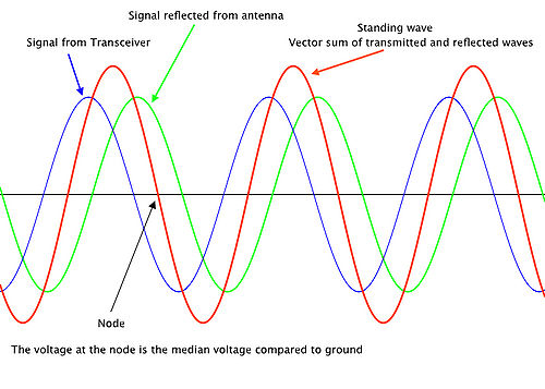
When there is a mismatch between the output impedance of a transmitter and input impedance of an antenna, some of the signal - in the form of a wave - is reflected back down the transmission line to the transmitter. Standing waved of electrical energy will "appear" in the transmission line. SWR is the ratio:
Amplitude (height) of the standing wave : Amplitude of an adjacent node (central point on the wave form)
The most commonly used SWR measurement is Voltage SWR or VSWR. Current SWR or IVSWR is rarely used but provides the same information. The diagram above can be thought of as representing either voltage or current.
If the feedline has no loss, and has the same impedance as the transmitter output and the antenna input impedance, then maximum power will be delivered to the antenna. In this case the VSWR will be 1:1 and the voltage and current will be constant over the whole length of the feedline.
The proportion of power to the antenna that is reflected back down the feedline is known as reflected power. It is determined by the reflection coefficient <math> \rho </math> at the antenna, given by:
<math> \rho = \frac{Z_1 - Z_0} {Z_1 +Z_0} = \frac {E_r}{E_f} </math>
where:
<math> Z_1 = </math> antenna impedance
<math> Z_0 = </math> feedline impedance
<math> E_f = </math> forward voltage - towards the antenna
<math> E_r = </math> reflected voltage
<math> VSWR = \frac {1+ \sqrt (\frac{P_r}{P_f})}{ 1- \sqrt(\frac{P_r}{(P_f})} </math>
where:
<math> P_r = </math> reflected power
<math> P_f = </math> forward power - towards the antenna
Some myths about SWR
1) I can calculate SWR to a ratio of 1.000 : 1
Most instruments do not operate that this level of accuracy
2) High SWR is bad
Look here for very detailed discussion about SWR
3) My SWR meter is the best on the market so is infallible
Any instrument that is placed between the transmitter and the antenna changes the characteristics of the transmission line.
4) High SWR will interfere with my neighbours TV
Your transmissions are most likely to interfere with other services when:
- your transmitter puts out a broad band signal rather than a narrow band signal
- the TV station that your neighbour is watching is on a frequency that is a harmonic of your TX frequency
- you are using high power into a beam that is at the same height and directed towards your neighbours TV antenna
How is SWR calculated?
Briefly, use an SWR meter, but better still - see the above discussion about SWR calculations until someone puts more information in this section or look at the following links:
Online SWR calculator from VE3KL
