Gate Spring Dipole: Difference between revisions
No edit summary |
No edit summary |
||
| Line 1: | Line 1: | ||
== A Shrunken Dipole with Loading Coils == | |||
[[User:G4juv|Neil]] built this dipole which uses farm gate springs as loading coils. You can get an 80 metre dipole into quite a small space. Of course you lose efficiency but this is for people with less than 40 metres of back garden. | [[User:G4juv|Neil]] built this dipole which uses farm gate springs as loading coils. You can get an 80 metre dipole into quite a small space. Of course you lose efficiency but this is for people with less than 40 metres of back garden. | ||
| Line 44: | Line 46: | ||
I have seen articles that recommend the loading coil goes in the middle of the wire stretch or at the feed point. I attended a lecture by an antenna specialist who made it clear that the high current parts of the antenna should be as large as possible so putting the loading coil at the feed point might tune correctly but will be less efficient. | I have seen articles that recommend the loading coil goes in the middle of the wire stretch or at the feed point. I attended a lecture by an antenna specialist who made it clear that the high current parts of the antenna should be as large as possible so putting the loading coil at the feed point might tune correctly but will be less efficient. | ||
== External Links == | |||
*[http://www.radiowymsey.org/FanDipole/slinky.htm M0WYM Slinky Dipole] | |||
*[http://www.nonstopsystems.com/radio/frank_radio_antenna.htm N4SPP Slinky Dipole] | |||
*[http://www.eham.net/articles/23260 N1FDX Slinky Dipole] | |||
*[http://www.ki6yfq.com/projects/slinky_dipole_antenna.html KI6YFQ Slinky Dipole] | |||
{{antennas}} | {{antennas}} | ||
Revision as of 05:28, 12 May 2011
A Shrunken Dipole with Loading Coils
Neil built this dipole which uses farm gate springs as loading coils. You can get an 80 metre dipole into quite a small space. Of course you lose efficiency but this is for people with less than 40 metres of back garden.
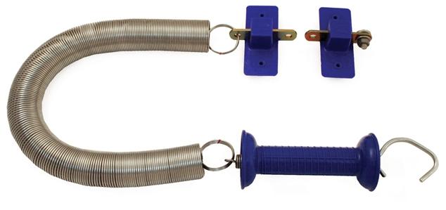
Visit your local farm supplies store or go on-line and buy two kits like this. Get stainless steel if you can.
Make the dipole using the longest wire length that will fit your limited space. Mount it as high as possible. Mine is set up as an inverted V.
Use an ATU to tune it up and you are done. If you have an antenna analyser, it should be possible to optimise the antenna by tweaking the wire lengths and the amount of stretch in the loading coils. This should result in a more efficient antenna.
More Details
This is an 80 metre dipole that fits in a small space. An ATU is needed and using the ATU, the antenna works on other bands too. It is ideal for portable use because of its small size.
This antenna idea came from various websites where the metal slinky toy had been pressed into use for an antenna. The slinky suffers from corrosion and is really only suitable for indoor use.
What was needed was an outdoor, heavy duty, corrosion resistant slinky. The electric fence gate spring fitted the bill. Get ones that stretch up to 5 metres. They are available on line too.
Discard everything apart from the springs. Now build your dipole. The wire should be as long as your available space permits. I used about 5 metres on each leg.
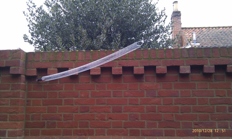
The spring need not be stretched far but make sure the turns are not touching, even in strong wind.
My gate spring could not be soldered so the wires were attached with screw down chocolate blocks, well greased with silicone to slow corrosion at the contact points.
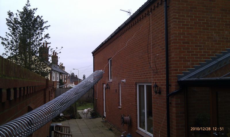
My antenna was mounted as an inverted vee with the ends about 2.5 metres above ground. The centre feed was about 6 metres above the ground. This configuration is likely to have a high radiation angle, good for more local contacts. For a lower radiation angle, mount it vertically or as near to vertical as possible. An inverted L might also work but both these configurations might have more unbalanced feeder currents.
Using an antenna tuning unit suitable for balanced line, this could be brought to 1:1 SWR on 80, 40 and 20 metres but not 160 metres. Using four springs might work for top band. "Fourspring Durch Technik"!
Within minutes, I had QSOs from the UK to Italy and the Channel Islands so the antenna works. Obviously a full size dipole will work better but this is a nice idea for a site with limited space. This whole exercise was done on guesswork. If I ever have time, I might use an antenna analyser to see if the design could be improved. Proper resonance on 80 metres would be a good start.
To make the antenna work better, experiment with the amount of spring stretch and the length of the wire sections.
I plan to raise the entire antenna using three poles, two at the ends and one in the centre. This should reduce losses, raise the feed impedance and improve the efficiency of the antenna. There is space for a longer antenna. This one was cut to length using all my available wire.
I have seen articles that recommend the loading coil goes in the middle of the wire stretch or at the feed point. I attended a lecture by an antenna specialist who made it clear that the high current parts of the antenna should be as large as possible so putting the loading coil at the feed point might tune correctly but will be less efficient.
External Links
| Antennas | |
| Design | Beam * Dipole * Dish or Parabola * DDRR * Log Periodic (LPDA) * Loop * Mobile and portable * Omnidirectional * Panel * Quad and Quagi * Screwdriver * Small tuned loop * Vertical * Yagi-Uda * Wire and random wire antennas |
| Installation | Antenna Tuners * Capacity hats and loading coils * Cavity filters * Coaxial Cable * Feedlines * Rotators * Towers and Masts * VK2ACY - G5RV coupler |
| Theory | Front-to-back ratio * Impedance matching * SWR * Tower design * Vertical Antenna efficiency * Wire comparison tables |


