Dish or Parabola
Related wiki pages:Antennas, Gain, Propagation, SWR
A number of sources have been used to gain information for this page - including the excellent online microwave antenna book by Peter Wade W1GHZ. The diagrams are original.
Parabolic Geometry
A Parabola is one of the “conic sections” and is defined as the locus (path) of a point that travels so that it is equidistant from a fixed point and a straight line. Algebraically this can be reduced to:
<math> y = ax^2</math> where a is a constant
More specifically, <math> y = \frac{x^2}{4f} </math> where f is the focal length – distance from the curve to the focal point
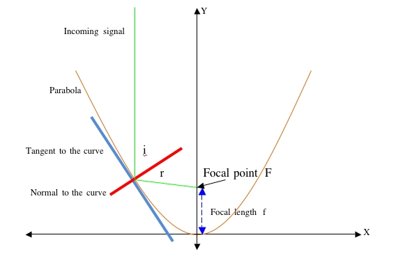
In the diagram above:
- the Y axis is central to the curve
- the tangent is a line that touches the curve at one point and has the same gradient as the curve at that point
- the normal is perpendicular to the tangent at the point of contact with the curve
- i is the angle of incidence – the angle between the incoming signal and the normal
- r is the angle of reflection – the angle between the reflected signal and the normal
- i = r Angle of incidence = Angle of reflection
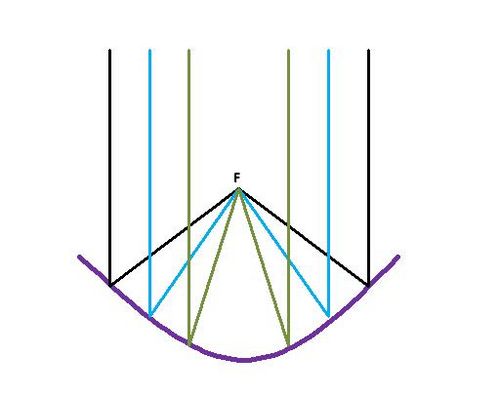
- a broad beam entering the parabola will be reflected to and concentrated at the focal point
During receive, the signal is concentrated at the focal point F. During transmit, energy emmitted at the feed point at F will produce a beam of RF energy.
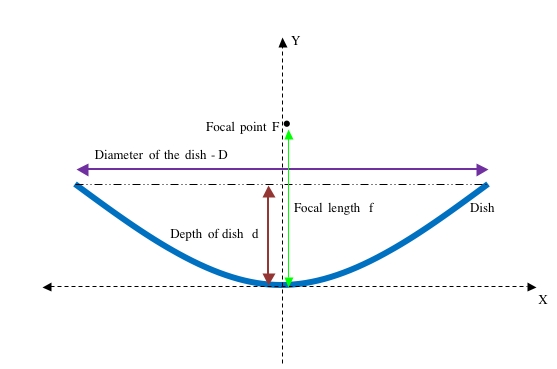
Finding the focal length of a parabolic dish
<math> f = \frac {D^2}{16d} </math> where D is the diameter of the dish and d is the depth of the dish
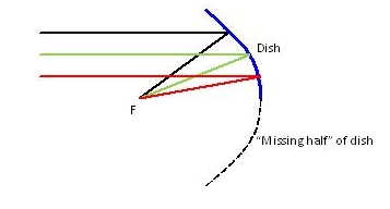
Offset-fed dish antenna
Many small dishes are effectively "half' of a parabola. The feedpoint is at the focal point F
Gain of a dish antenna
Related wiki page - Gain
the gain of a dish antenna (compared to an isotropic standard) can be calculated thus:
<math> Gdbi = 10\times \mbox{log} \left( \eta \frac {4 \pi}{\lambda^2}A \right) </math> where:
<math> \eta </math> is the efficiency of the dish
<math> A </math> is the area of the dish
<math> \lambda </math> is the wavelength of the signal
The efficiency is perhaps the most difficult variable to maximise - generally 50% is considered to be reasonable, but 70% - 80% can be achieved with very good feeds.
For practical purposes, the most critical measurement affecting the gain (regardless of dish size) of a dish antenna has been found to be placing the feedpoint exactly at the focal length f. Paul Wade - W1GHZ, gives the following relative gain measurements for a 22inch dish with <math> \frac{f}{D} =0.39 </math> operating at 10GHz:
Links to dish construction projects
| Feed distance | Relative gain |
| 8.125" | -0.6dB |
| 8.250" | 0dB |
| 8.375" | -0.3dB |
| 8.625" | -1.7dB |
| Antennas | |
| Design | Beam * Dipole * Dish or Parabola * DDRR * Log Periodic (LPDA) * Loop * Mobile and portable * Omnidirectional * Panel * Quad and Quagi * Screwdriver * Small tuned loop * Vertical * Yagi-Uda * Wire and random wire antennas |
| Installation | Antenna Tuners * Capacity hats and loading coils * Cavity filters * Coaxial Cable * Feedlines * Rotators * Towers and Masts * VK2ACY - G5RV coupler |
| Theory | Front-to-back ratio * Impedance matching * SWR * Tower design * Vertical Antenna efficiency * Wire comparison tables |


