Oscillator Design
Related wiki pages Amplifier Design, Power Supply Design.
Fundamentals
An oscillator is an electronic circuit designed to produce either audio or radio frequency signals. These will generally have sineusoidal wave form, but other wave shapes such as square and sawtooth are possible. In radio equipment oscillators will always have a low output power, and if a radio frequency is produced, the oscillator is acually a basic radio transmitter.
In oscillators, the following are deliberate design parametes:
- frequency production
- amplification
- positive feedback, also known as regeneration
These factors are also present in amplifier operation. Hence design is important as amplifiers should not be oscillators!
Frequency Production
Oscillator frequency is usually produced using a resonant LC ciruit or a quartz crystal. Quartz crystals are used where frequency stability is important. See Piezoelectric Effect for more information about quartz crystals. If an LC oscillator is used it should have the following characteristics for maximum stability.
- there should be a high C to L Ratio
- a well regulated power supply should be used
- there should be good isolation between the oscillator and its load
- components should exhibit little change in value with changing temperature
- the oscillator itself should be isolated as much as possible from large temperature changes
Buffer amplifier
A buffer amlifier is used to improve frequency stability by isolating the oscillator from its load. It is required bacause of the low power produced by oscillators. Drawing on this low power shifts the frequency of the oscillator. Buffer amplifers will have high impedance so that they draw no power from the oscillator.
Drift
Drift refers to changes in oscillator frequency due mainly to capacitance changes in the circuit as a result of temperature fluctuations. Drift can be controlled by having the tuning capacitance large compared to the tuning inductance
Types of Oscillator
Armstrong
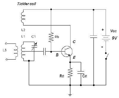
The Armstrong oscillator L1 and C1 on the base of the transistor determine the frequency of operation - C1 is variable allow the frequency to ve varied. This oscillator is distinguished by the use of a "tickler coil" L2 in the circuit below. L2 is inductively coupled to L1, providing some positive feedback (regeneration) to the input of the transistor.
- Rb determines the bias current.
- The bias current flows from earth through Re into the emmitter, out through Rb to the positive
- Re provides emmitter current stabilisation and prevents thermal runaway
Hartley
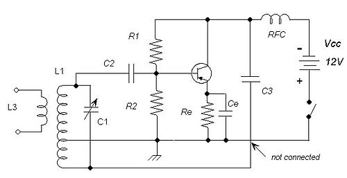
The Hartley oscillator has a tickler coil like the Armstrong oscillator but it is part of the "front end' of the circuit. In the diagram below the tickler coil is the lower part of L1.
Clapp
Colpitts
| Electronic Theory | |
| Physical quantities | Current * Gain * Impedance * Power * Q of a circuit * Radiated Power Measurement * Reactance* Resistivity * Resonance * Voltage |
| Components | Baluns * Bipolar-Junction Transistors * Capacitors * Diodes * Inductors* Lasers * Microphones * Resistors * Transformers * Wire |
| Circuits | Attenuators * Digital Signal Processing (DSP) * Dummy load * Filters * LC filters * Power Supply Design * Rectifier Circuits |
| Design | Amplifier Design * Oscillator Design |
| Electromagnetic Waves | Relative power (Decibels) * Harmonics * Interference and BPL |
-


