Attenuators
Revision as of 21:15, 21 December 2008 by TimVK4YEH (talk | contribs) (→How is attenuation measured?)
Related wiki pages; Apparatus, Dummy Load
What is an attenuator?
An attenuator is a resistive device that reduces the amplitude of a signal without adding distortion to it. The amplitude of a radio signal is the power, so an attenuator is used to reduce the power of a transmission.
Attenuator Circuits
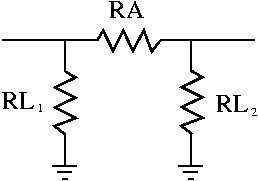
The pi circuit
In the circuit below, known as a pi pad;
- RA = Arm resistor
- <math>RL_1</math> = leg resistor 1
- <math>RL_2</math> = leg resistor 2
Approximate resistor values for a single pi pad are as follows
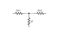
The T circuit
In the circuit below, known as a T pad;
- RL = Leg resistor
- <math>RA_1</math> = Arm resistor 1
- <math>RA_2</math> = Arm resistor 2
Approximate resistor values for a single T pad are as follows
| Attenuation dB | Arm resistor | Leg resistors |
| 3dB | 17.6 | 292.4 |
| 6dB | 37.4 | 150.5 |
| 10dB | 71.2 | 96.2 |
| 20dB | 247.5 | 61.1 |
When would we use one?
- When making transmission measurements using highly sensitive equipment. The attenuator reduces power to protect the measuring equipment.
- To produce low power for QRP transmissions. many modern HF rigs have a minimum power out of around 5 Watts. QRP operators usually use powers well below this.
How is attenuation measured?
Attenuation is measured in decibels (dB) of relative power. A guide to the attenuation-dB relationship is:
| Attenuation dB | Arm resistors | Leg resistor |
| 3dB | 8.5 | 141.9 |
| 6dB | 16.6 | 66.9 |
| 10dB | 26 | 35.1 |
| 20dB | 40.9 | 10.1 |
| dB | Attenuation | Power in | Power out |
| 3dB | 0.5 | 100W | 50W |
| 6dB | 0.25 | 100W | 25W |
| 10dB | 0.1 | 100W | 10W |
| 20dB | 0.01 | 100W | 1W |
| 30dB | 0.001 | 100W | 0.1W |

