Gain: Difference between revisions
(antenna comparison table) |
|||
| Line 15: | Line 15: | ||
''Pe'' = 3, ''Pi'' = 1 | ''Pe'' = 3, ''Pi'' = 1 | ||
<math> 10 \times \log \left( \frac {3}{1} \right) = 4.77\mbox{dBD} </math> | <math>10\times\log\left(\frac {3}{1}\right) = 4.77\mbox{dBD} </math> | ||
===Gain compared to an isotropic radiator = dBi === | ===Gain compared to an isotropic radiator = dBi === | ||
Latest revision as of 01:17, 22 November 2010
Related wiki pages Antennas, Antenna Design, Decibels, Radiated Power Measurement, SWR
What is Gain?
Gain compared to a half wave dipole - dBD
The gain of an antenna is the relative increase in radiation at the maximum point expressed as a value in decibels (dB) above a standard. The standard to which other antennas are compared is usually a ½-wavelength dipole. The standard antenna is given a reference gain of 0dBD (zero decibel referenced to dipole). This comes from:
<math> \mbox{gain} = 10 \times \log \left( \frac {Pe}{Pi} \right) </math>
Where Pe is effective radiated power and Pi is input power
An antenna with the effective radiated power of three times the input power would therefore have a gain of:
Pe = 3, Pi = 1
<math>10\times\log\left(\frac {3}{1}\right) = 4.77\mbox{dBD} </math>
Gain compared to an isotropic radiator = dBi
An isotropic radiator is a theoretical "point source" antenna that radiates the same amount of energy in all directions. Although an isotropic antenna cannot be constructed, it is sometimes useful to compare actual antennas to it.
Comparison of dBD and dBi
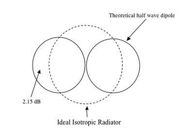
Graphically, the radiation patterns of isotropic and dipole antennas - for equal power inputs - can be represented thus:
The area between the isotropic radiator circle and the half wave circle radiator circle represents a gain difference of approximately 2.15dB
hence, <math> dBi = dBD + 2.15 </math>
Comparative gain of various antenna types
| Antenna Type | dB gain over isotropic radiator | dB gain over half-wave dipole |
| Isoptropic radiator | 0 | -2.1 |
| Ground plane | +0.3 | -1.8 |
| half-wave dipole | +2.1 | 0 |
| 5/8 wave dipole | +3.3 | +1.2 |
| Quad loop single element | +4.1 | +2 |
| 2 element yagi | +7.1 | +5 |
| 3 element yagi | +10.1 | +8 |
| 4 element yagi | +12.1 | +10 |
| 2 element quad | +9.1 | +7 |
| 3 element quad | +12.1 | +10 |
| 4 element quad | +14.1 | +12 |
Adapted from Orr WL (W6SAI) and Cowan SD (W2LX), 1986, the Radio Amateur Antenna Handbook
dBo Optical Gain
dBO is an unofficial term used by some amateurs working with transmission of data using light. It refers to the apparent gain of an optical system compared to a point source of light.
| Electronic Theory | |
| Physical quantities | Current * Gain * Impedance * Power * Q of a circuit * Radiated Power Measurement * Reactance* Resistivity * Resonance * Voltage |
| Components | Baluns * Bipolar-Junction Transistors * Capacitors * Diodes * Inductors* Lasers * Microphones * Resistors * Transformers * Wire |
| Circuits | Attenuators * Digital Signal Processing (DSP) * Dummy load * Filters * LC filters * Power Supply Design * Rectifier Circuits |
| Design | Amplifier Design * Oscillator Design |
| Electromagnetic Waves | Relative power (Decibels) * Harmonics * Interference and BPL |
