Attenuators: Difference between revisions
Jump to navigation
Jump to search
(page need repair, I can work out how to fix the positions of the tables :() |
mNo edit summary |
||
| (6 intermediate revisions by 2 users not shown) | |||
| Line 1: | Line 1: | ||
Related wiki pages; [[Apparatus]], [[Dummy Load]] | Related wiki pages; [[Apparatus]], [[Dummy Load]] | ||
= What is an attenuator?= | |||
An attenuator is a resistive device that reduces the amplitude of a signal without adding distortion to it. The amplitude of a radio signal is the power, so an attenuator is used to reduce the power of a transmission. | An attenuator is a resistive device that reduces the amplitude of a signal without adding distortion to it. The amplitude of a radio signal is the power, so an attenuator is used to reduce the power of a transmission. | ||
=When would we use one?= | |||
* When making transmission measurements using highly sensitive equipment. The attenuator reduces power to protect the measuring equipment. | * When making transmission measurements using highly sensitive equipment. The attenuator reduces power to protect the measuring equipment. | ||
| Line 25: | Line 25: | ||
Approximate resistor values for a single pi pad are as follows | Approximate resistor values for a single pi pad are as follows | ||
[[Image:Pi_pad.jpg | 300px]] | |||
=== The T circuit === | === The T circuit === | ||
| Line 50: | Line 40: | ||
Approximate resistor values for a single T pad are as follows | Approximate resistor values for a single T pad are as follows | ||
[[Image:t_pad.jpg | 300px]] | |||
=== The H circuit === | |||
Also known as the H pad or I circuit(I pad) | |||
=== The O circuit=== | |||
Also known as the O pad. | |||
==Online attenuator calculators== | |||
* [http://www.nu9n.com/tpad-calculator.html T and H pad calculators]from NU9N | |||
* [http://www.softpedia.com/progClean/Attenuator-Calculator-Clean-119756.html Attenuator calculator 1.2] Attenuator calculator software. | |||
* [http://chemandy.com/calculators/pi_attenuator_calculator.htm Pi calculator] | |||
* [http://www.daycounter.com/Calculators/PI-T-Pad-Attenuator-Calculator.phtml Pi and T pad calculator] | |||
| Line 82: | Line 79: | ||
|---- | |---- | ||
|----|} | |----|} | ||
{{electronics}} | |||
Latest revision as of 20:39, 27 July 2009
Related wiki pages; Apparatus, Dummy Load
What is an attenuator?
An attenuator is a resistive device that reduces the amplitude of a signal without adding distortion to it. The amplitude of a radio signal is the power, so an attenuator is used to reduce the power of a transmission.
When would we use one?
- When making transmission measurements using highly sensitive equipment. The attenuator reduces power to protect the measuring equipment.
- To produce low power for QRP transmissions. many modern HF rigs have a minimum power out of around 5 Watts. QRP operators usually use powers well below this.
Attenuator Circuits
The pi circuit
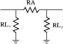
In the circuit below, known as a pi pad;
- RA = Arm resistor
- <math>RL_1</math> = leg resistor 1
- <math>RL_2</math> = leg resistor 2
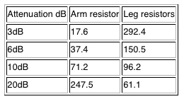
Approximate resistor values for a single pi pad are as follows
The T circuit
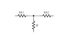
In the circuit below, known as a T pad;
- RL = Leg resistor
- <math>RA_1</math> = Arm resistor 1
- <math>RA_2</math> = Arm resistor 2
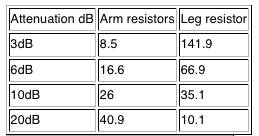
Approximate resistor values for a single T pad are as follows
The H circuit
Also known as the H pad or I circuit(I pad)
The O circuit
Also known as the O pad.
Online attenuator calculators
- T and H pad calculatorsfrom NU9N
- Attenuator calculator 1.2 Attenuator calculator software.
How is attenuation measured?
Attenuation is measured in decibels (dB) of relative power. A guide to the attenuation-dB relationship is:
| dB | Attenuation | Power in | Power out |
| 3dB | 0.5 | 100W | 50W |
| 6dB | 0.25 | 100W | 25W |
| 10dB | 0.1 | 100W | 10W |
| 20dB | 0.01 | 100W | 1W |
| 30dB | 0.001 | 100W | 0.1W |
| Electronic Theory | |
| Physical quantities | Current * Gain * Impedance * Power * Q of a circuit * Radiated Power Measurement * Reactance* Resistivity * Resonance * Voltage |
| Components | Baluns * Bipolar-Junction Transistors * Capacitors * Diodes * Inductors* Lasers * Microphones * Resistors * Transformers * Wire |
| Circuits | Attenuators * Digital Signal Processing (DSP) * Dummy load * Filters * LC filters * Power Supply Design * Rectifier Circuits |
| Design | Amplifier Design * Oscillator Design |
| Electromagnetic Waves | Relative power (Decibels) * Harmonics * Interference and BPL |


