QTH
There are multiple systems in use for identifying location (QTH) using zones or grid squares.
Zone systems
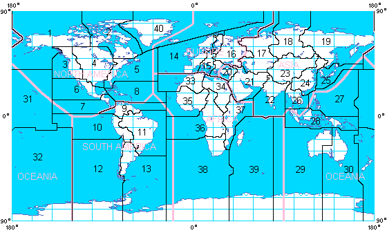
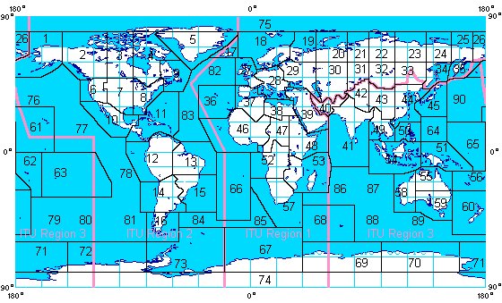
A number of systems exist to divide the world into zones and regions. In some cases, the divisions and numbering schemes are arbitrary, as with the CQ Zone and ITU Zone systems often used to identify a station's location on QSL cards.
CQ Zone
The CQ Zone system, originally devised by CQ Magazine, divided the world into forty arbitrary zones.
ITU Zone
The ITU Zone system, devised by the International Telecommunications Union, is similar but uses 89 zones in three regions. ITU Region 1 is Africa, Europe and Russia, Region 2 includes all of the Americas, Region 3 is Australia and southern Asia.
Grid squares
See Gridsquares
The zone systems represent an arbitrary division; a simple algorithm would not readily be able to estimate distance between two points based on a zone number pair. A more systematic approach would to be to use a latitude and longitude grid, such as WGS84.
In order to reduce the length of a pair of geographic co-ordinates when transmitted in Morse code, various schemes have been used to abbreviate grid square identifiers based on latitude and longitude.
QRA Locator
The original QRA-Locator system, devised in Germany and adopted by the VHF Working Group in The Hague in October 1959, was based on geographical longitude and latitude using a grid with an origin of (0°W, 40° N) to provide coverage of Europe. Two letters would indicate an individual grid square; this would be followed by two numbers to sub-divide the grid into smaller squares. While a fifth character was added at the 1963 Region 1 Conference in Malmö (1963) as a further sub-division, this five-character QRA-Locator system remained unable to cover the entire globe without codes being repeated. This system was therefore replaced by a rival system devised by John Morris, G4ANB and adopted at a meeting of VHF managers in Maidenhead, England in 1980.
IARU/Maidenhead Locator
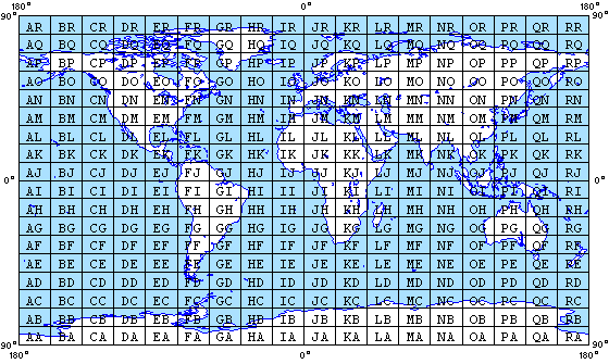
The IARU Locator (also known as the QTH Locator or Maidenhead Locator System) is based on a division of the globe, by latitude and longitude, into an 18 x 18 grid with origin (AA) at (90°S, 180°W). The system is based on the WGS84 co-ordinates and each 10° latitude x 20° longitude field is in turn divisible into a 10 x 10 array of "squares", each 1° x 2° in size. Each of these may then be further divided into "subsquares", using a 24 x 24 array.
The resulting code is sent as two letters (field), followed by two numbers (square) and optionally two more letters (subsquare). For instance, (0°N, 0°W) would be abbreviated as JJ00aa.
As lines of longitude converge at the north and south poles, the divisions created by this system are not, in fact, square. They may appear to be rectangular on some maps, depending on the projection used.
Much like political and geographical divisions have been used as entities for QSL collection for HF awards (Worked All Continents, Worked All Britain, Worked All States, DXCC), the individual grid squares have been used as the basis for collection of awards by VHF and UHF radioamateur operators. A typical contest objective would be the establishment of contact with stations in one hundred different grid squares on a given band or mode from one location.
External links
- All about locators, SARL
- The Maidenhead Locator System, Folke Rosvall SM5AGM
- The locator system, QRZ.ru
- Grid Locators and Grid Squares, ARRL
- Locator and zone maps, G3NPF & M1AIM
- AMSAT grid square converter
- Online Maidenhead QTH locator, F6FVY
| Operating procedures | |
| Operation | Callsigns and ITU prefixes * Codes and Alphabets * Modes * Morse code * Nets * UK licensing * Terminology |
| DX and Contesting | Awards and Certificates * DXCC * DX cluster * Field day * Gridsquares * Logging * QSL and QSL Bureaus * Records - Distance |
| Emergencies | Emergency Frequencies * ARES * IRESC * SATERN * Weather spotting |
| QRP | Trail-Friendly Radio |
| Utilities | Beacons (/B) and Time Beacons |


